

It’s an enduring truth that appearances can be deceiving, especially with electrical systems. When I inspected Summer Dance before buying her, the electrical system looked like one of the boat’s strong suits. It had an upgraded panel and a new battery. The wiring was all original except for spliced connections to the panel. There weren’t any added accessories so the system was simple and I expected it to be relatively problem-free. Granted, I’m no marine surveyor and if I had ordered a survey, it would have caught many of the problems that I later discovered.
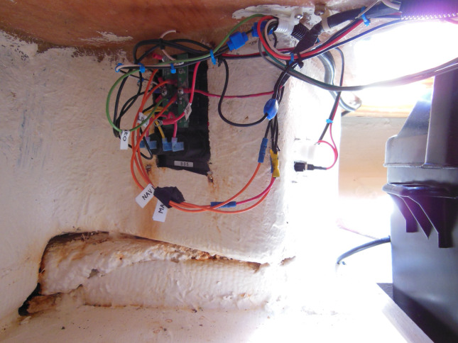
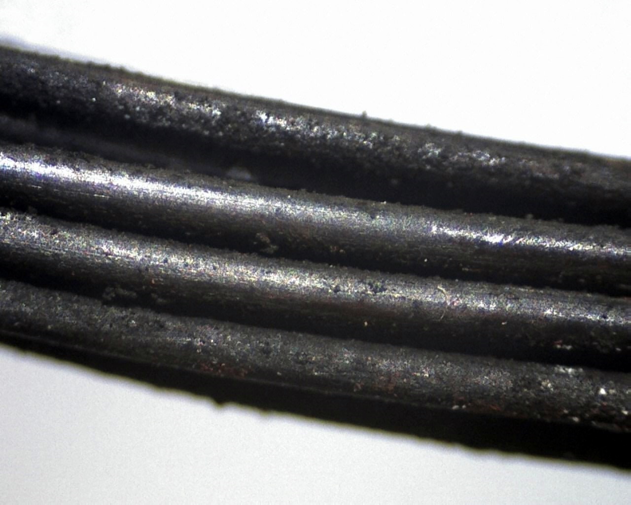
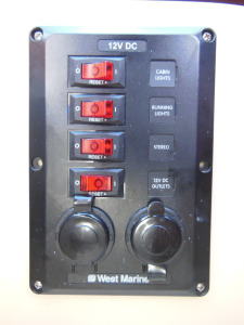
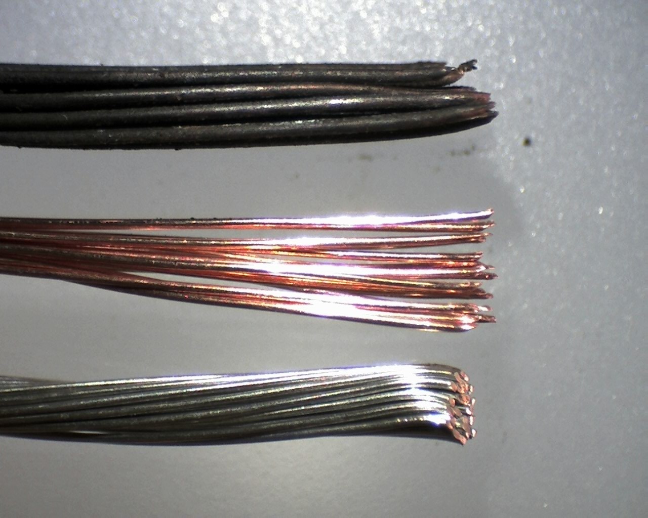
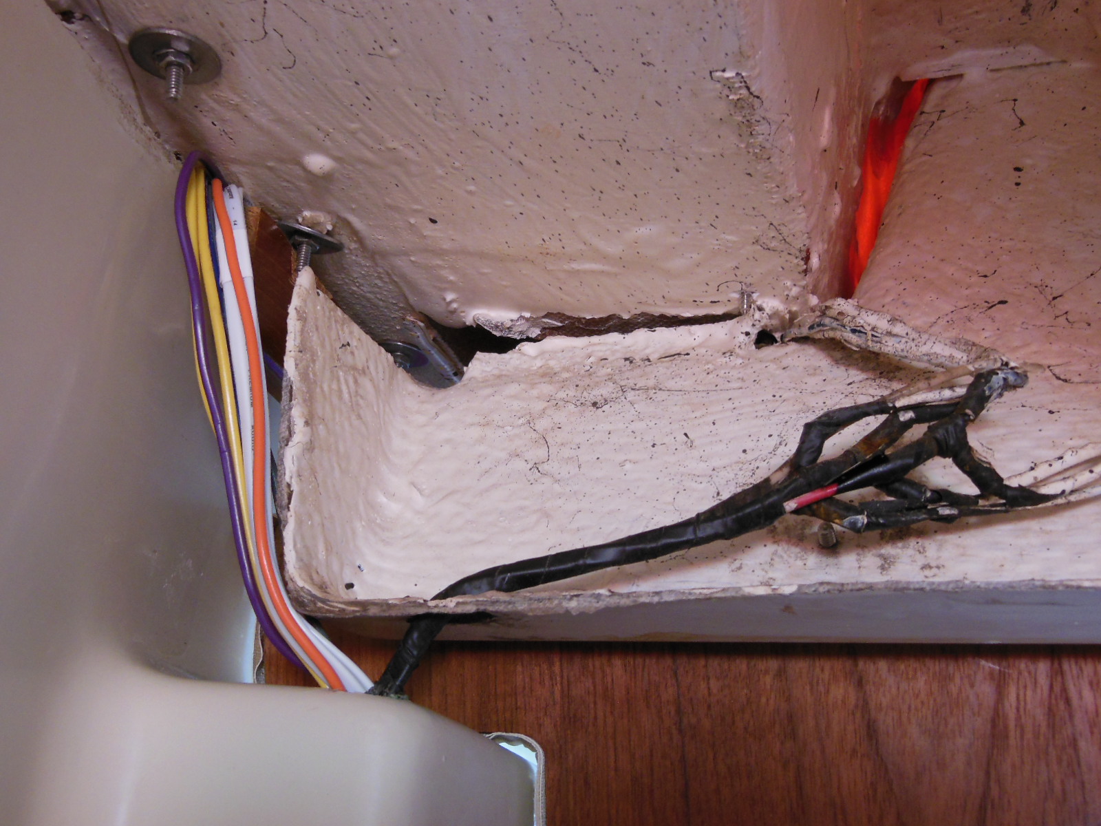
The first problem that I had was an intermittent stern light connection. Next was an intermittent primary ground wire. When I removed and disassembled the West Marine breaker panel to clean it, all the spade connectors had some level of salt water corrosion. Then the main ground conductor failed entirely and I had to replace it. Upon further inspection, all the conductors to the battery and breaker panel showed extensive corrosion for several feet under the insulation that made them brittle and prone to breaking. There was no overcurrent protection at the battery at all. Since electrical system failures are a major cause of onboard fires, it’s also true that what you cannot see can hurt you.
When I started adding accessories like the music system, LED strip lights, anchor light, and autopilot, it became clear that the four circuit panel was going to be inadequate.
Rather than connect the new accessories to an unsafe and crumbling foundation, I decided to rewire the boat so that everything was new and built (as close as practicable) to the American Boat and Yacht Council standard E-11 – AC & DC Electrical Systems on Boats.
I say “as close as practicable” to the ABYC standards because the ABYC is intended for boat manufacturers and service centers, not boat owners. Their standards documents are not generally available to the public. You have to pay an expensive membership fee and then purchase the standards for $195. Those costs would exceed this project’s entire cost for materials–not exactly practical for the average boat owner–let alone the $tingy Sailor. However, excerpts of the current standard are also available online for information like the wiring size tables and color codes.
Disclaimer: I make no claims that the methods described in this article meet the current ABYC E-11 standard in any way. The reader is solely responsible for any consequences of following this advice and is encouraged to seek professional assistance if they are unfamiliar with this subject.
Planning a new electrical system consists of:
- Take inventory of the existing and planned devices
- Group the devices into like-function circuits
- Calculate the total potential load of each circuit
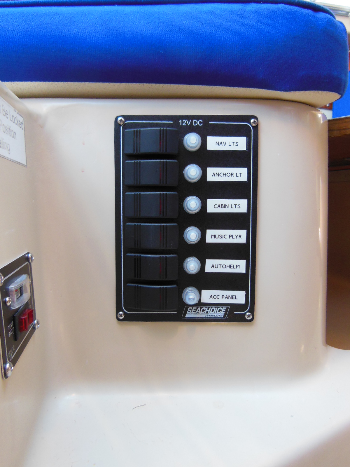
- Select a new panel with at least as many breakers as the planned circuits
- Assign the circuits to adequately sized breakers in the new panel
- Measure the round trip distance to each device from the panel or other connection location
- Calculate the correct wire gauge and determine the color for each circuit according to the E-11 tables
- Draw a schematic diagram of the location of each device and its conductors for easy reference

When you know all of the wire lengths, gauges, and colors that you’ll need, you can order the marine grade wire, heat shrink crimp connectors, and other installation supplies from online retailers like GenuineDealz.com and Del City. For reference, this project cost me about $220 in 2013.
With all the supplies in hand, the installation is pretty straightforward if you’re familiar with DC power systems. If not, I recommend that you read a good book about marine electrical systems like Sailboat Electrics Simplified by Don Casey.
What follows are some installation tips from my project that are specific to the C-22 or similar trailerable sailboats.
Battery wiring
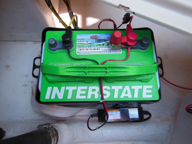
Your sailboat likely has a single, deep cycle battery, and no starter motor. To meet the 7″ overcurrent protection rule, install an MRBF type fuse block on the positive post. If you have an outboard motor charging circuit (fused) or an onboard shore power charger, connect them upstream of the fuse block. You might also consider installing a battery master switch if you have a really complicated system and long wire runs. If you’re planning to install a solar panel to charge your battery, check out Solar panels for boats: an easy installation guide.
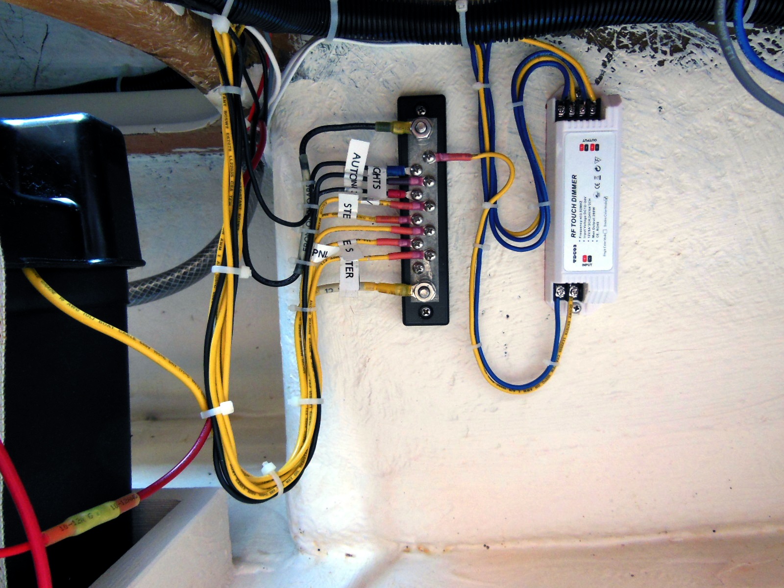
Ground bus bar
The original wiring in most small sailboats has no separate bus for the negative conductors. Instead, all connections terminate at the breaker panel. Adding a dedicated negative bus bar really helps to organize the wiring and simplifies the panel connections.
Accessory panel
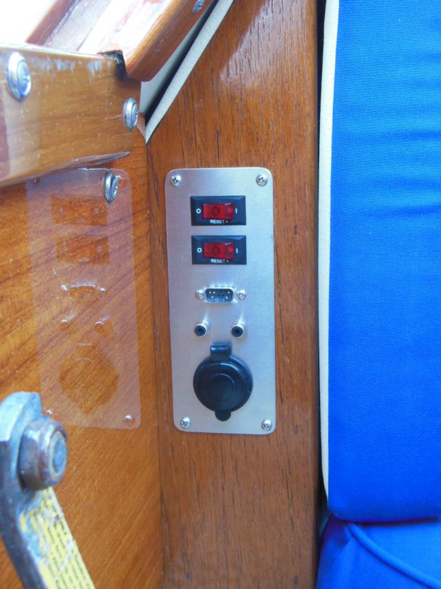
Besides the power wiring, I also had some signal wiring to accommodate: the NMEA signal from the GPS to the autopilot and the stereo rear channel speaker signals for connecting to my crib board mounted cockpit speakers. I also wanted to install two 12V power outlets in convenient locations in the boat. I also needed to mount a switch for the lazarette LED strips. I solved all these issues by fabricating an aluminum accessory panel and mounted it in the wood trim next to the companionway. The panel makes it easy to connect my handheld GPS to power and the autopilot, switch on the lazarette lights, and connect the cockpit speakers. I installed an extra switch for future use. I installed the other 12V outlet in the side of the stereo enclosure where it’s handy for connecting an oscillating fan.
Wiring concealment
The original wiring in C-22s (and I suspect in many other small boats) is mostly embedded in the fiberglass itself. This makes the wiring mostly invisible but it also makes it mostly unserviceable. So, you can’t replace all the old wiring with new, you have to install the new wiring and abandon the old in place. This also means that you have to find places to contain and conceal the new wiring.
The best place for this in the cabin area of a C-22 is in the channel formed by the hull to deck joint. The channel runs nearby most places where you will want to mount lights and accessories. In first generation C-22s, this channel is covered by teak trim that you can easily remove. I found it helpful to tape the wires in place until I was finished installing them and then replace the trim. A notable exception is the mast wiring jack. There’s nowhere to conceal new wiring to the jack in the deck near the mast step. Since mine had never been connected before, I used the existing wiring, which was still like new. If you don’t want to use the existing wiring, you can mount a cable to the cabin ceiling behind the curtain track or in some kind of covering.
Other good locations are the underside of the hull liner for traversing the hull and the underside of the cockpit sole for running wire aft. I used 3/4″ flame retardant (required per E-11) split loom held in place with wire ties (18″ max. apart per E-11) through self-adhesive mounting pads. In older boats like mine, you might need to clean the mounting locations first with rubbing alcohol or another solvent to insure good adhesion. The mounting pads won’t stick to old, chalky paint.
Since replacing the wiring, I haven’t had a single electrical problem. I know exactly what every wire is and I can access every inch of it if a problem ever does come up. More than likely, I’ll make more modifications and upgrades.
Would you like to be notified when I publish more posts like this? Enter your email address below to subscribe to this blog and receive notifications of new posts by email. You will also receive occasional newsletters with exclusive info and deals only for subscribers and the password to the Downloads page. It’s free and you can unsubscribe at any time but almost nobody does!

What program did you use to create the wiring diagram?
Hi, Richard
I use Microsoft Visio 2013 for all my line drawing needs that don’t require high precision, 3D, or aren’t very complex. For those, I either use Google SketchUp for quick and dirty modeling or AutoCAD for doing the heavy lifting. All of these programs are vector-based, so making changes in them is very easy as opposed to raster image-based programs like Windows Paint or PhotoShop that are best for photo editing.
Thanks! Great site BTW. I have a Precision 21 and all of the projects you’ve done on the C-22 are appliçable to my boat as well. You’ve given me a lot of ideas for new boat projects. Don’t know whether to thank you or curse you 😉
Thanks, for looking outside the Precision camp, Richard. There’s no prejudice around here. All brands all welcome!
You can thank me. Your wife might have the cursing covered for ya 😉
It really looks well organized. After buying a jaguar 22 last year I replaced the original wiring in a way to prevent incidents and to be able to sail the first season. Your site helps me planning the jobs for this season and especially rewiring the proper way.
I hope all storm damages were repaired and you and the first mate will be enjoying sailing again this season.
Thanks for your kind words and I hope you find all the information you need here. If not, let me know!
MVG
Have a look at “Tinycad” for an excellent electrical drawing package
I love your site and thank you for the detailed wiring instructions. I have purchased my first boat, a 1978 Catalina 22, and the wiring is quite sliced and diced. I am purchasing the Seachoice panel and ground block. Is there a location where the terminal ground block grounds to on the boat, or is it just to the battery. Currently I have to hit the fuse panel to get it to work SCARY
Nope, only directly to the battery. There is no common ground like the frame of a car so every circuit needs a companion ground conductor, hence the greater need for strategically placed ground bus bars in the sailboat.
Hello, and thank you for all the great information you share with all of us. It is greatly appreciated here! We have a 22ft Catalina and are rewiring it completely. Could you tell us what AWG you used for your cables? We don’t want to make mistakes and burn our beautiful boat! Thanks
Hello, Edward
There really is no one size that fits all. The correct wire size depends on the length of the circuit and the load of all devices on the same circuit. Consequently, I used several different sizes. That’s why I said in the article to measure the round trip distance to each device from the panel and calculate the correct wire gauge according to the E-11 tables. That’s the only way to be safe and avoid a potential overload condition.
Thanks for your question!
I am interested in adding LED lighting to my Catalina 270LE. There are two main areas I would like to have them. One is in the aft cabin (“The Cave”) and the other in the main cabin up both sides to and including the sides of the V-berth.
I don’t know what LED strips to use but found these: https://tinyurl.com/y865ndnh
which I think can work (?) but idk about a switch or if they should go on the same breaker/wiring as “Cabin Lights”, which currently has 9 non-LED (stock?) lights wired to it. I was going to remove them and install their LED doppelgangers on their wiring.
I’m a bit new to electricity, having only done car and home stereo stuff mostly before this. I’m pretty good at reverse engineering/putting things back together they way they came apart, so I have some confidence in some other projects on my yacht such as replacement of a faulty GFCI outlet.
Hello, Behr
Those LED strips should work for you but you might consider a lower light temperature. 6000K is a very harsh, white light. Something in the 3000-4000K range is still bright but a warmer, more natural color. As for which circuit to attach them to, it depends on how many strips you want to attach (24W each) and the other loads on the same circuit. You should total all the expected loads and the wire lengths, then calculate the correct AWG size according to the ABYC E-11 tables. If it’s the same as your existing wiring, then you’re good to go. If it exceeds your existing wiring, then you either need to reduce the load or increase the wire size to avoid overheating the wiring or tripping the breaker, which also should not exceed the ampacity of its attached conductors. If you want to operate the strips independent of the dome lights, then you will need to install a switch before the light strips.
I really like the difference that the light strips make and so does the first mate 🙂
I’m about to tackle this project and was wondering where and how you installed your negative bus bar? Also, did you use jumper wires on the negative posts at the switch panel vs. running individual lines in and out? Thanks so much for another great article! I can’t imagine working on my boat without your site.
Hello, Kevin
I installed my negative bus bar adjacent to the battery inside the aft settee locker. I used a couple of small machine screws with lock nuts on the backside. The switch panel that I used has a single negative connection to the bus bar. Short jumpers distribute that connection to the individual breaker switches. The positive side of each switch has dedicated conductors to its corresponding device. There’s also a dedicated positive conductor to the switch panel that powers the switch indicator lights. That’s the red conductor that you see at the bottom of the “cover” picture for this post and the red jumpers on the left side of the picture.
Good luck with your project!
Still need to tidy up the wiring but thanks to your advice I now have a working switch panel and lights! Thank you!
In your diagram above, I don’t see the navigation lights. I see the bow, but not the side lights. e.g. port and starboard. Am I missing something? I need to tackle this project as my boat has no battery or electricity, and I have been using it for three years. 😦
On C-22s the bow light is the side navigation lights in one unit installed either on the deck or on the pulpit.
Great site! Thanks
On my C-22, both sides are built into one light. But if you have separate bow lights, you would connect them in series in the same circuit anyway, so the diagram would be very similar.
Can you clarify when you say round trip calculation for the wiring. Seems it is only one way, i.e. from panel to a light. I do appreciate your valuable information so thanks.
Hi, wuzz802
It’s round-trip because you have to also run a ground wire to each device – there is no chassis ground like a car.
Thanks for your question,
$tingy
Very clear and concise article. I rewired my Tayana 37 in much the same way. I found the wiring to be much the same; original non-tinned wire with significant corrosion. The only solution was to rewire this 45 year old boat from the keel up. I noted no bilge pump in your wiring diagram. I have 3 on my boat that are directly switched, wired, and fused to my house batteries. Is there a bilge pump on the boat or are they self bailing? You do not mention wire connections. Don Casey’s book covers this topic but may be worth mentioning.
Hi, Tom
You’re correct. I don’t have an electric bilge pump on my boat, but I do have a portable manual pump and a collapsible bucket. I keep my bilge bone dry so the only points of water ingress are: 1) failure of the keel cable volcano hose, which is easy to spot 2) major hull puncture or 3) knockdown with hatches open (avoidable). In cases 2 and 3, the average bilge pump probably won’t solve the problem by itself and I’ve got bigger issues to solve anyway. Plus, I’m loathe to drill a new hole in a 42 year-old boat for a through-hull fitting.
My goal for the article was primarily to provide information that skippers couldn’t easily find in other sources like Casey’s books, not to cover every nuance, which would fill up another book, LOL.
$tingy
Hi thanks so much for all the great information! I think it’s in a different post but when you drilled into the “dimple” to find the mast wiring… How far down was it? I’ve drilled down maybe 2″ and found a void (1996 c22 mk-2) ..but the void is only about a 1/2″ seam… No wires that I can find. Do I need to drill further? I drilled a 3/4 wide hole in the middle of the dimple
Did you reach in with a coat hanger or other tool and fish around for the wires? They likely won’t be directly under the dimple. At least mine weren’t.