

You want to refinish your C-22 swing keel the right way, so you’re planning to buy the Swing Keel Refinishing DVD from a certain Catalina parts dealership. It’s been around for over 15 years and is the de facto authority on how to do the job. I’m sorry to break it to you, but if you use the template that’s included with the DVD to fair your keel, it will prevent you from getting the best performance out of your keel.
What follows is a detailed analysis of the template, the geometry of the C-22 swing keel, and the undesirable results the template produces when used to fair the keel during refinishing. If you don’t care about the hydrodynamic performance of your sailboat or don’t intend to refinish your swing keel, this post might not interest you—but don’t stop following this blog. I’ve got some cool DIY projects coming soon that have nothing to do with hydrodynamics. On the other hand, if you’re planning to refinish your swing keel some day and you want to get the most bang for your hard-earned bucks, sweat, and hours of labor, read on to avoid disappointing results.
A template for error
The DVD is advertised as including “A 13% foil template for reshaping the stock keel into a higher performance, more efficient shape.”
This means that the goal of the template is to make a standard NACA 13% foil shape for minimum drag and maximum pointing ability at the average hull speed of the C-22. You use the template to fair the shape of your keel when you refinish it as described in the previous post in the series, Refinishing your swing keel for best performance – Part 3: Fairing.
You cut the template shape out of a piece of thin plywood that is easier to use. You hold the wooden template perpendicular to the keel center line (as shown in the video and in the picture below), to check the keel shape and thickness as you add the fairing compound.

Unfortunately, the template that comes with the DVD is the wrong shape.
The template has a quote printed on it that reads:
“The actual foil percentage if the (keel hanging) angle was 45 degrees, the water length would be 22.62″, which would come out to 13.2%. This is about perfect for a small boat. Generally, a 10% is preferred for higher speeds, but the cross-section is usually too weak. The 13% has better stall characteristics at slower speeds.” Al Gunther
Al appears to have been (and might still be) a Catalina 27 owner that was active in a couple of online sailing forums, not a Catalina designer or otherwise related to Catalina Yachts. I suspect his quote was taken out of context for the DVD or he was speaking generally, not specifically about the C-22. He could not be contacted for comment.
How 45° does not equal 30°
Regardless of the bad grammar, the word “if” is the key.
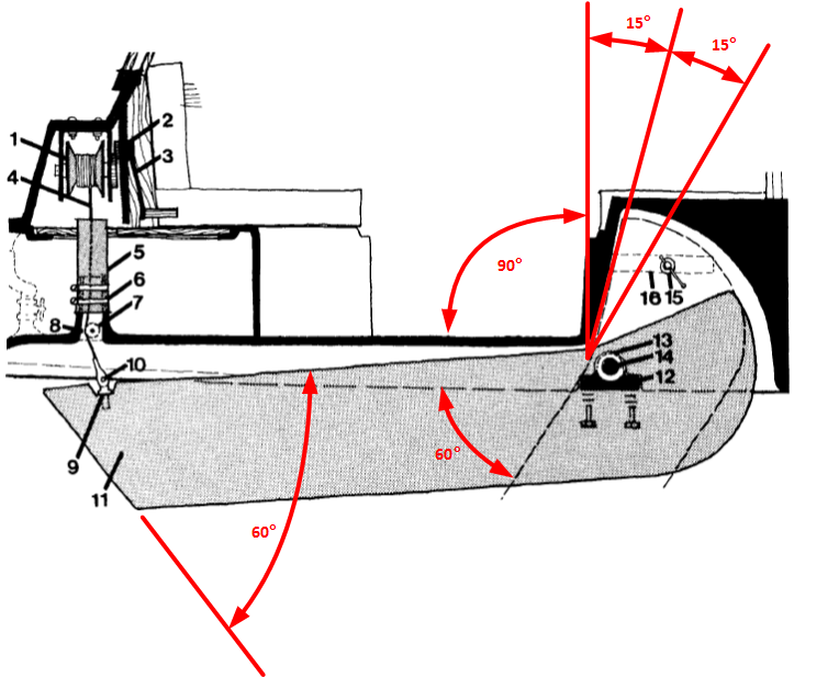
The first problem with the template is that the C-22 swing keel angle is 30° swept back from vertical as shown in the following drawing, not 45° as stated on the template and in the video.
The bottom end of the keel is horizontal when the keel is lowered. The angle of the end of the keel to its edges is 60°. Likewise, the angle of the front of the trunk where the keel rests when lowered is 15° from vertical. The angle of the edge of the keel that rests against the front of the trunk is also 15°. 15° + 15° = 30° and 90° – 60° = 30°.
Nothing about the design is 45°. Why the producer of the DVD didn’t know that is anyone’s guess. To the Catalina parts dealership’s credit, they didn’t produce the video. It was produced by Robert Trim of Trim Entertainment Services, a C-22 owner who could not be reached for comment.
But why the video or template hasn’t been corrected by now and is still sold that way by people who ought to know better after all these years is inexplicable. When I asked the Catalina parts dealership about the discrepancy, they didn’t deny there was an error, claimed that none of the hundreds of DVD customers have ever asked about it, it wasn’t calculated by them, and it would take them a day of research to figure it out. Their final response was, “If you trying to be that anal about it, buy another boat.” Caveat emptor.
If the math doesn’t convince you, below is a picture of Chip Ford’s C-22 named Chip Ahoy with the keel lowered. If you import that picture into any vector-based PC software, rotate the picture 2° clockwise to level the hull, and measure the angle of the keel, it will be 30° from vertical.

If you think a difference of 15° is much ado about nothing, think again. Any keelboat designer will tell you the angle is significant because it determines the water length—the distance that water flows across the keel in its lowered position. The water length is also the length of the foil shape that you want to fair the keel to match. Consequently, the foil shape determines the template shape.
How the template misses the mark
The caption on the template clearly states “NACA 13%” so you might think that you’re looking at a 13% foil template but you’d be wrong as I’ll now explain. This is where understanding the keel shape and its geometry can be confusing. It’s all about the math but hang in there with me while I get my armchair engineer on and you’ll find out why it matters. Read the rest of this section slowly and carefully and you’ll be alright.
The National Advisory Committee for Aeronautics (NACA) is the agency that tests and catalogs standard foils in aeronautics for use by NASA, Boeing, Airbus, almost every professional and hobbyist airplane and boat designer, and even bicycle designers. Imagine the cross-section of an airplane wing and you’ll get the right idea. Since water and air are both fluids, aeronautic flow characteristics also apply to keels and rudders. They simply work in water instead of air.
The names of standard NACA foil shapes include the thickness of the foil expressed as a percentage of its length (also known as its chord). So the width of a NACA 13% foil is 13% of its length. The higher the percentage, the thicker the shape relative to its length, more like a teardrop.
Despite the caption on the template, it is not a 13% foil curve but is meant to produce a 13% foil in the water when the keel is lowered to 30° from vertical. It is actually a 19% foil curve that produces a 16.5% keel as I’ll explain in a moment.
The water length of the keel’s foil shape when in its lowered position is longer than the curve of the template when held at 90° during fairing as shown in the following picture. Compare the three dimensions shown in red. The dashed keel outline hanging vertically is hypothetical only to show the template length at the same angle at the assumed and real water lengths. The keel never hangs at that angle under normal conditions.

So to wind up with a 13% foil in the water, we need to start with a template that has the same length as the keel width (so we can work with it at 90°) and the template (full shape) width should be the same as the width of a 13% foil at 30° from vertical.
Curses, foiled again!
That’s it for the theory. Now let’s look at the reality. If you measure the template (only one half is drawn so that you can measure the keel surface with it) you will find that it is 15.75″ long and 1.5″ at its widest. (Second generation keels are 3/4″ wider at 16-1/2″). Double the width to find the total thickness of the foil and you get 3″. The thickness is the key measurement because that is what is affected by your fairing. The width of the keel and the angle at which it hangs will remain the same regardless of how you fair the shape.
For a NACA 13% foil, thirteen percent of 15.75 equals only 2″, so you might ask yourself what is going on with the 3″ total thickness produced by the template. They can’t both be right now that we understand the relationship of the foil shape to the thickness and the real angle of the keel.
If you recall your high school math class formula for calculating the hypotenuse of a right triangle (![]() ), the 30° angle means that the real water length is 18.19″, not 22.62″ as stated on the template, which assumes a 45° angle. This shorter real water length means that the template produces a fatter effective foil than 13%—one whole inch fatter, to be exact, the difference between 2″ and 3″.
), the 30° angle means that the real water length is 18.19″, not 22.62″ as stated on the template, which assumes a 45° angle. This shorter real water length means that the template produces a fatter effective foil than 13%—one whole inch fatter, to be exact, the difference between 2″ and 3″.
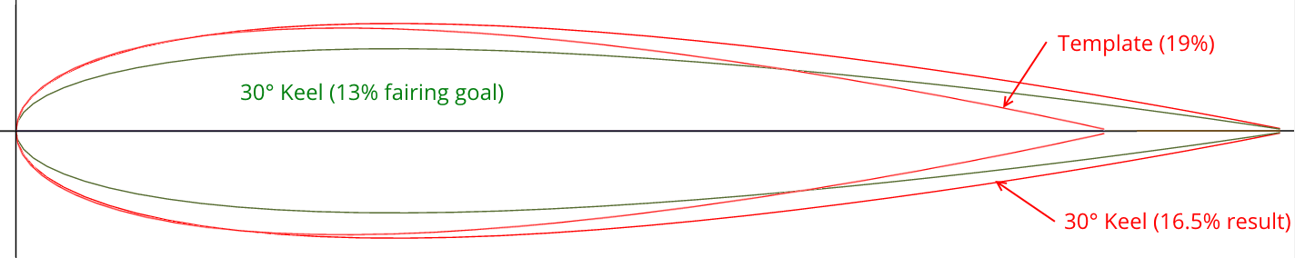
In fact, a NACA foil with an 18.2″ chord length (water length) and 3″ thickness is 16.5%, 3.5% more than the design goal. The same thickness foil at 15.75″ long (the template) is a NACA 19% foil. These are the red curves shown below. The template should be a 15% curve to produce a 13% foil (green curve below).
At the end of the day
The bottom line is, if you use the so-called 13% template (that’s actually a 19% template), you will get a 16.5% keel that creates more drag than it should and will need much more (I estimate between one and two gallons) expensive fairing filler to make. More drag means less speed. The keel will do pretty well at slow speeds but will stall sooner at higher speeds than a 13% keel. When keel stalling happens, leeway increases and the boat won’t point as high into the wind. Precisely how much it would affect your performance depends on a lot of variables: boat speed, wind speed, angle to wind, keel algae, and more.
That’s an unwanted handicap for C-22 racers. I can’t imagine how many C-22 racers in the last 16 years have used that template thinking they had the perfect keel shape, not knowing that they were off the mark. If that includes you, you’re probably familiar with Catalina 22 class rule C: Keel:
They shall remain unmodified in composition, size and shape. Refinishing the surface of the keel shall not be considered a modification.
Fortunately, when I contacted the C-22 class rules committee for comment, they replied that they interpret the rule to mean that as long as the profile shape and cross-section are not radically changed, such as by adding wings or a bulb, customary refinishing is accepted without requiring measurements. Race on, DIY keel refinishers!
What’s a skipper to do?
To get a 13% keel using the methods described here, you need to use a NACA 0015 (15%) template.
If you’re already a follower of this blog, in an email newsletter at the end of this series, I will send you a link to download an Adobe PDF file that I created that you can print on your home printer to make your own template. It will have instructions printed right on it. If you’re not already a follower, subscribe right away and you’ll receive the newsletter and link too. But don’t wait too long, there’s no newsletter archive that you can go back to and find the link.
If this hydrodynamics stuff is interesting to you and you’d like to see computed graphs of the differences in lift, drag, and stall angles of these foil shapes, then I invite you to download and read Keel and Rudder Design by David Vacanti that originally appeared in Professional Boatbuilder magazine. There are a lot of other good design resources online too.

I can now join in on conversation at a dock party when somebody brings up keel foil chord and 13 degrees.
Even though my Potter-19 moves too slow with me in it, I am not convinced that this magic number of 13 should work with all fluid densities, like freshwater versus salt water versus air.
It seems to me that fluids of different densities would have their different shapes to move through them at different velocities.
Sea turtles have a foil shape greater than 13% I believe.
You’ll probably hear more conversations around 12% (more optimal for cruiser/racer sailboats) or 10% (rudders/racers). Thirteen percent just happens to be the opinion of Al Gunther for some unspecified, hypothetical keel.
You make a good point about fluid density, which I left out of my explanation for the sake of simplicity. In fact, calculating the optimal foil shape for any particular application must take into account the Reynolds number of the flow conditions in which the foil will operate. That’s why airplane wings, helicopter rotors, and the like are generally flatter foils than barracudas, trout, sharks, and sea turtles.
Maybe your Potter has the hydrodynamics of a sea turtle? 😉
I am interested in that PDF with the 13% template. Could you point me to where I can download it?
“If you’re already a follower of this blog, in an email newsletter at the end of this series, I will send you a link to download an Adobe PDF file that I created that you can print on your home printer to make your own template. It will have instructions printed right on it. If you’re not already a follower, subscribe right away and you’ll receive the newsletter and link too. But don’t wait too long, there’s no newsletter archive that you can go back to and find the link.”
The template will be available for download at the end of the series in two weeks but only to subscribers. To receive the link, subscribe to this blog for free by clicking the Follow button in the sidebar on the right and entering your email address. You will then receive my newsletter by email that contains bonus information, late breaking news, special offers, and other opportunities just for subscribers as my thanks for following this blog. If you want to stop receiving the newsletter at any time, you can cancel your subscription by using the link at the bottom of the email.
I found you on Sailboat Owners forums and very excited about your knowledge of re-working the swing keel of your Clipper Marine 22 (I hope that’s right). I have a CM21, 1974, (new to me) and have done countless hours of research trying to find schematics, or even pictures of my Clipper Marine 21, although I do now have the Owner Manual.
When sailing in some real wind on the Columbia Gorge last summer, Her keel pivot bolt and the locking bolt started leaking and the keel went to banging. I thought that keel was gonna bust the hull apart before I could unfurl and raise the keel. Needless to say, I started researching and subsequent tare-down….AND…Here I am. I have pictures (posted on Sailboat Owners but not sure if I did it right) of Her keel-trunk tare-down if you want to see them. I do know She was NOT ‘fixed’ right (maybe ever?) and that there are enough differences between a CM and a C to need more (you’re help) info before putting my girl back together the right way!!
Can you help me PLEASE? Even simple sketches from memory will help. Also, I am NOT removing the keel, I have her jacked-up above her trailer just fine to access all repairs. Thank you for sharing your experience and knowledge so generously! I am eagerly awaiting your reply.
Columbia Gorge, huh? It’s a small world. I’m 15 minutes north of Spokane.
Your pictures look like there is a sheave mounted in the trunk that turns the keel cable and that sheave tore out?
Use the Contact page from the About menu and send me an email and we can discuss it offline.
Excellent, as always.
So if a guy just found you and followed your blog, where could he get the template? I currently have the keel off my 1978 C-22 on a pallet in my garage, sealed and smoothed flat with the first layer of glass…
Sent you a private email. Thanks for following!
Like bryan says,
I also have mine hanging in the shed with epoxy dripping fresh from the sandblasters. I did one ten years ago, just like the video except used all West 105/205, 407. That one is SO FAT, I want this one to be right.
Don Woodhouse
Sooz Moose 2134 (Race boat)
Togarty 7260 (Cruiser)
Currently preparing to drop the keel on my 1985 MacGregor 25. Based on the info in this blog about the NACA 13% foil, am I correct in assuming that a similar shape would be appropriate for my keel?
If so how can I receive the fairing template described in the blog?
BTW I just happened upon your $tingy Sailor website. It is just the resource I need to rehab my Mac 25! Thanks for your help.
Al Aymer
Unnamed new-to-me Mac 25
Hi, Al
I’m no expert on the Mac 25 but I suspect that you’re correct and a NACA 13% foil (+/- 1%) would be close to appropriate for your keel, assuming you don’t race it. However, since your keel is larger than the C-22 keel, the template available from the Downloads page here won’t be the right size. You’ll need a little larger template. You can try to blow up that template so that it matches the width of your keel or you could plot a NACA 0013 foil to match your keel width at airfoiltools.com. Enter 0, 0, and 13 in the first three boxes on the first page and then click Plot. After it redraws the foil, click Send to airfoil plotter. On the next page, enter the width of your keel in mm in Chord and then click Plot. After that redraws, use one of the links to either download a PDF file or open the plan in a new window to print. Print it out so that the length matches the width of your keel.
Now, these instructions don’t compensate for your keel’s angle, so you’ll have to apply the math that I explain in the post above but using your actual measurements. You’ll have to plot a larger than 13% foil so that when it is stretched out to the water length of your keel foil when the keel is lowered, the resulting foil is 13%. If your keel hangs at 30 degress like the C-22 keel, then 15% should do the trick for you too.
Lastly, the template is necessary for the C-22s primarily because their cast iron keels are so irregular and inconsistent. I’m not familiar with how the Mac 25 keels are constructed but I suspect that they are more consistent and accurate than the C-22s, so you may not need a template at all. If your keel has a pretty consistent shape and is not badly damaged, you can probably just fair it smooth to its current profile and be done with it.
Best of luck refinishing your keel. It’s a tough job but worth doing. Let us know how it turns out for you!
$tingy
Thanks for the quik response, $tingy. I’m still mulling over what I’m going to do but if I proceed your information should prove useful.
After reading you response and the method of plotting fhe foil for my Mac25, I have an additional question. Where keel width is entered in mm under CHORD, does that width refer to the cross-sectional measurement or the “fore-to-aft” measurement of the keel?
The chord length is the perpendicular cross-section of the keel.
$tingy Sailor, thanks for this awesome series of articles. I am about to fair, printed off the template and was surprised that the max width of is less than 2 /12 inches. That makes sense given 15% of 15.75 is 2.36. But it seems pretty thin as the blog was talking about 3 inches. So just to validate, I’m good to target a the 2.36 inch real physical width? I do understand the 30% keel angle has the effect of increasing that width. Thanks again!
Hi, Andy
I’m not sure why you’re aiming for 15% instead of 13%. If you want 13% then your keel should be only 2″ thick. Depending on how your keel was cast, that might mean taking off a lot of material, particularly at the bottom.
i am targeting 13%, and using your template, in mid project right now. You article and tools have been invaluable. Thanks again!
Glad to be of help!
I enjoy your web site as I’m in the process of refitting a 1974 Catalina 22.
Thanks for all this info. I’m looking at buying and restoring a boomaroo 22 (Australian Catalina) and your blog and vids are invaluable especially as i need to do on the cheap.
Can I still get the template? I’ve just stripped and sealed my 85 Cat 22 keel. Thanks
Sure. Just sign in to the Downloads page and click on the picture.
Hello, I am new at this since I bought a Catalina 22 just 3 months ago and haven’t sailed her yet. Great blog. very informative.
I am interested in that PDF with the 13% template. Could you point me to where I can download it?
Best regards and good sailing, Reinier
Hi, Reinier
Congratulations on your new-to-you C-22!
You can download the template from the Downloads page.
$tingy
My boat is a 21ft swing keel similar to the Catalina 22, however, considering the thickness and the waterline length of the keel, I’m getting NACA numbers of 16% when factoring in the 60 percent slope, which approximately equals a naca 18for my template. I can only assume that the keel was built differently, with a thicker keel compared to its length. Is this a red flag? are there other boats in the naca 16 ratio? unfortunately, a ‘spirit 6.5’ doesn’t have much info online
Hi, Dan
Are you sure that your keel is angled to 60 degrees and not 30 degrees? Regardless, NACA 16 or 18 might be correct for your boat. The only way to know is to find out the original design shape, which could be impossible. Unless you plan on high level racing or are a performance nut like me, I’d recommend just fairing the current shape as symmetrical, consistent, and smooth as possible. That’ll probably work just fine for you.
Let us know how your keel turns out,
$tingy
How can I get the template?
Carol,
If you are a follower of my blog, you received a password that you can enter in my Downloads page at https://stingysailor.com/downloads-faq/. Then you can download the drawing from the list of files that appears.
Thank you for all the great info you post Stingy.
I bought a 83 Catalina 22 just over a year ago. I had the local marina here in Corpus Christi paint the bottom and the keel. 9 months later I pulled it out of the slip and the paint is just falling off the keel. It’s like they just painted over the rust. Since I have it at home now and on boat stands I’m going to attempt to do what you did. I was wondering where I can get the fairing template. I’m a subscriber but I think I came on board a little too late for the newsletter link.
Thanks,
David
Hi, David
When you subscribed, the confirmation email included the password to the Downloads page at https://stingysailor.com/downloads-faq/ where you can find the template. If you can’t find that email, send me a private message from the Contact page of the site and I’ll send it to you after I confirm your subscription.
Best of luck with the project,
$tingy
Good day I’m in need of a link to download an Adobe PDF file for a 13% keel using the methods from the NACA 0015 (15%) template.
Hi, Austin
You can download the drawing for free from the Downloads page at https://stingysailor.com/downloads-faq/ if you’re a subscriber. If you’re not yet a subscriber, you can do so by entering your email address at the bottom of any page.